Conventional Cone-Beam CT Scanner. Describing hardware geometrical characteristics

In Cobra detector positions in every spot of its trajectory are defined by the terms of a central ray and a central ray crossing point.


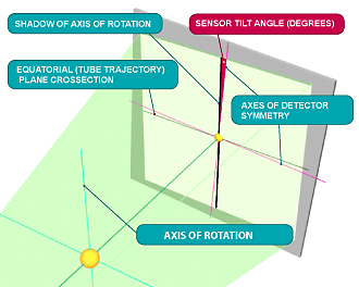
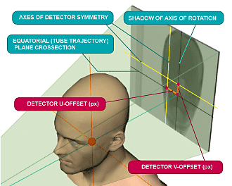
Central ray is the ray coming from a focal spot of x-ray source and perpendicular to the axis of rotation. In ideal cone-beam CT central ray trajectory forms an ideal plane usually called as equatorial plane.


Central ray crossing point is the point where a central ray is crossing the detector

Detector pivot (tilt)

Detector pivot (tilt)

Detector offsets

Detector offsets


Describing detector positions


To make an accurate reconstruction it is necessary to know positions of source and detector in every spot where x-ray beam exposes an object.  Cobra utilizes the following parameters illustrated on this page.


Horizontal and vertical distances between a central ray crossing point and a physical center of the detector (called in Cobra U- and V- offsets)


Detector pivot (tilt): detector rotation angle around its norm measured relatively a projection (“shadow”) of axis of rotation

top_bord

Describing a reconstruction task

Within the COBRA reconstruction package, all input, output and intermediate data are kept on the hard disk. The user defines and controls the reconstruction task through a parameter file, a text file with extension .xxm. This file contains tags and assigned values, and describes the scanner hardware setup, input and output data characteristics and representation, and the chosen reconstruction method. Some of the reconstruction options are only accessible through SDK API’s. These are related to synchronization and control of in-line reconstruction (recon concurrent with acquisition), and the setup of COBRA’s working folders.
block_bord_bot
bord_bot top_bord

Tags controlling scanner geometry

PARTAG_SRCOBJDIST

PARTAG_SRCOBJDIST

Defines: distance in mm between X-ray source and origin (rotation center)
Value type: float
Default value: 500
PARTAG_SRCDETDIST

PARTAG_SRCDETDIST

Defines: distance in mm between X-ray source and detector
Value type: float
Default value: 1000
PARTAG_SCANANGLE

PARTAG_SCANANGLE

Defines: scan angle in degrees (angle of rotation of the gantry or rotational table)
Value type: float
Default value: 360
PARTAG_STARTANGLE

PARTAG_STARTANGLE

Defines: angle in degrees where scan was started (controls angular orientation of the object in the output cube)
Value type: float
Default value: 0
PARTAG_INVERSEANGLE

PARTAG_INVERSEANGLE

Defines: If set to 1 then angle counts in the angle.bin file must be inverted (to support different angle.bin conventions). Not relevant when angle.bin is not present.
Value type: integer (can be 0 or 1)
Default value: 0
PARTAG_PROJRECON

PARTAG_PROJRECON

Defines: Number of projections (input views) to reconstruct
Value type: integer
Default value: 360
PARTAG_DETOFFSETU

PARTAG_DETOFFSETU

Defines: Detector position horizontal offset in pixels (distance between the point where the central ray intersects the detector and the physical center of the detector)
Value type: float
Default value: 0
PARTAG_DETOFFSETV

PARTAG_DETOFFSETV

Defines: Detector position vertical offset in pixels (distance between the point where central ray intersects the detector and the physical center of the detector)
Value type: float
Default value: 0
PARTAG_DETPIVOT

PARTAG_DETPIVOT

Defines: Detector pivot (tilt) in degrees (detector rotation angle around an axis through its center and parallel to the axis of rotation)
Value type: float
Default value: 0
PARTAG_ROTATIONDIR

PARTAG_ROTATIONDIR

Defines: Gantry or turntable direction of rotation
Value type: integer (can be 0,1, or –1; 0 or 1 means CW; -1 means CCW)
Default value: 0
block_bord_bot
bord_bot
cobra_link